Contact Supplier
- Categories
- Electronics Product
- Beauty / Personal Care
- Furniture / Building Materials
- Automotive Machinery
- Ladies clothing
- Home Department Store
- International Logistic Service
 Electronics Product
 Beauty / Personal Care
  Furniture / Building Materials
  Automotive Machinery
  Home Department Store
  International Logistic Service
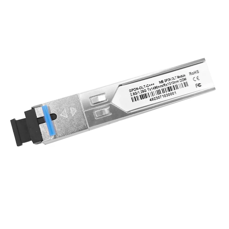
 COME-SFP-C+++9dB 9dBm GPON OLT C+++ 2.5G PON SFP Transceiver Module compatible with Huawei ZTE and Normal Brand GPON OLT.GPON OLT optical modules are classified into class B+, C+, C+, C+, and C++ based on their optical power. GPON module is an SFP hot-swappable optical module (Adopt ITU-T G.984.x) used for optical data communication links. It adopts single-fiber bidirectional design and has an uplink rate of 1.25Gbps and a downlink rate of up to 2.5Gbps.
Support single-fiber bidirectional hot-swappable SFP of SC, UPC, and APC
Central wavelength, Downstream 1490nm, upstream 1310nm
Support Get DDM parameters
Support transmission distance is up to 20KM
Support Compliant with MSA SFP specification SFF-8472
Support Conforms to the ITU - T G. 984. X
Gigabit Ethernet Passive Optical Networks (GPON CLASS C+++)-OLT side


The interface is an extension of the serial ID interface defined in the SFP MSA specificationThe specifications define a 256 byte memory map in E~PROM which is accessible over a 2wire serial interface at the 8 bit address 1010000X (A0h). The digital diagnostic monitoringinterface makes use of the 8 bit address 1010001X (A2h), so the originally defined serial IDmemory map remains unchanged. The interface is backward compatible with both the GBICspecification and the SFP MSA.
1. TX Fault is an open collector output, which should be pulled up with a 4.7K~10KI resistoron the host board to a voltage between 2.0V and Vcc+0.3V. Logic 0 indicates normal operation:logic 1 indicates a laser fault of some kind. In the low state, the output will be pulled to lessthan 0.8V.
2. TX Disable is an input that is used to shut down the transmitter optical output. It is pulled upwithin the module with a 4.7K~10K resistor. Its states are:Low (0_0.8V): Transmitter on
(>0.8V,<2.0V): Undefined
High (2.0~3.465V): Transmitter Disabled
Open: Transmitter Disabled.
3. MOD-DEF 0,1,2 are the module definition pins. They should be pulled up with a4.7K~10K resistor on the host board. The pull-up voltage shall be VccT or VccR.MOD-DEF 0 is grounded by the module to indicate that the module is presentMOD-DEF 1 is the clock line of two wire serial interface for serial IDMOD-DEF 2 is the data line of two wire serial interface for serial ID.4. LOS is an open collector output, which should be pulled up with a 4.7K~10K resistor onthe host board to a voltage between 2.0V and Vcc+0.3V. Logic 0 indicates normal operation:logic 1 indicates loss of signal. In the low state, the output will be pulled to less than 0.8V.5. These are the differential receiver outputs. They are AC coupled 1001 differential lineswhich should be terminated with 1009 (differential) at the user SERDES.6. These are the differential transmitter inputs. They are AC-coupled, differential lines with1002 differential termination inside the module.


Finding a reliable supplier and ensuring
error-free production can be overwhelming.
As a leading sourcing company in China,
We have hundreds of experrts who can handle
the entire sourcing process from finding
suppliers to delivering products.