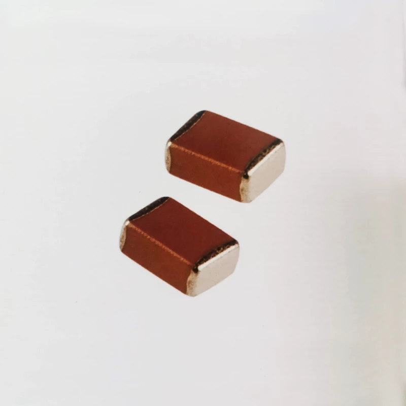
CT41L - Military multilayer ceramic capacitors
- Temperature range for use
- -55℃~+125℃或-55℃~+85℃
Characteristics and Applications
No external sealing layer, suitable for surface mounting;
The medium is Class II ceramic, with a high dielectric constant and a large capacitance to volume ratio of the capacitor;
Each batch of products undergoes 100% temperature shock screening and high-temperature electrical load screening;
Suitable for bypass, filtering, low-frequency coupling circuits in various military electronic equipment such as weapons, ships, aviation, and aerospace, or circuits with low requirements for loss and capacitance stability.
Ordering Example
| G | CT41L - 0805 - 2C1 - 50V - 104 K | |||||
| Quality Grade | model | External dimensions | Temperature characteristic | rated voltage | Nominal Capacity | Capacitance Tolerance |
| See the table below |
Class II porcelain medium Multilayer ceramic capacitor |
See the table below | See the table below | Direct standard method 50V | Numerical method, 104 is 100000pF | See the table below |
Comparison Table of Quality Levels and Execution Standards
| Quality Grade | Quality grade code | Refer to the general standard for execution | Detailed specification number |
| Seven specialties | G | QZJ840624 Ceramic Capacitor "Seven Specialized" Technical Conditions | Q/MC111-2019 |
| general military grade | J | GJB192B-2011 | Q/MC110-2019 |
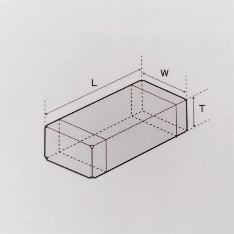
External dimensions
| Size Code | External dimensions(mm) | 备注 | ||
| L | W | Tmax | ||
| 0402 | 1.00±0.15 | 0.50±0.05 | 0.55 | CR<1.0μF |
| 1.00±0.15 | 0.50±0.15 | 0.8 | CR≥1.0μF | |
| 1.00±0.15 | 0.50±0.20 | 0.8 | CR≥10.0μF | |
| 0603 | 1.60±0.15 | 0.80±0.15 | 0.95 | CR<10.0μF |
| 1.60±0.30 | 0.80±0.30 | 1.1 | CR≥10.0μF | |
| 0805 | 2.00±0.20 | 1.25±0.20 | 1.4 | CR<10.0μF |
| 2.00±0.40 | 1.25±0.40 | 1.5 | CR≥10.0μF | |
| 1206 | 3.20±0.30 | 1.60±0.30 | 1.9 | |
| 1210 | 3.20±0.40 | 2.50±0.30 | 2.8 | |
| 1812 | 4.50±0.50 | 3.20±0.40 | 3.5 | |
| 2220 | 5.70±0.50 | 5.00±0.50 | 5.2 | |
| 2225 | 5.70±0.50 | 6.30±0.50 | 6.2 | |
Temperature characteristic
| Temperature characteristic code | Maximum allowable capacity variation | Working temperature range |
| X7R | ±15% | -55℃-+125℃ |
| X7S | ±22% | -55℃~+125℃ |
| X7T | -33%~+22% | -55℃-+125℃ |
| X6S | ±22% | -55℃-+105℃ |
| X6T | -33%~+22% | -55℃~+105℃ |
| X5R | ±15% | -55℃-+85℃ |
| X5S | ±22% | -55℃~+85℃ |
| 2R1 | ±15% | -55℃~+125℃ |
| 2R2 | ±15% | -55℃~+85℃ |
| 2C1 | ±20% | -55℃~+125℃ |
| 2C2 | ±20% | -55℃~+85℃ |
| 2X1 | ±15% | -55℃~+125℃ |
Allowable deviation of capacitance
| code | Allowable deviation range |
| K | ±10% |
| M | ±20% |
Main performance indicators
| item | Test conditions | performance index |
| capacitance CR |
1、Capacity List A: CR<100pF:1MHz±20%,1V±0.2Vrms CR≥100pF:1KHz±20%,1V±0.2Vrms 2、Capacity ListB: CR≤10μF:1KHz±10%,1V±0.2Vrms 10μF<CR<470μF: 120Hz±10%,0.5V±0.2Vrms CR≥470μF:50Hz±10%,0.5V±0.1Vrms |
1、Capacity List A: tg δ ≤350×10-4 2、Capacity ListB: a、0603 and below size, or products with a capacity greater than or equal to 1 μ F,tg δ ≤1200×10-4 b、UR≤16V,tg δ ≤1000×10-4; 16V<UR≤50V,tg δ ≤500×10-4; 50V<UR≤200V,tg δ ≤250×10-4; c、CR≥100μF,tg δ ≤1500×10-4 |
| loss tangent tg δ | ||
| insulation resistance IR | Test Voltage:rated voltage UR;Test time:1min±5s |
1、Capacity List A: CR≤25μF,IR≥4000MΩ CR>25μF,IR≥100MΩ·μF 2、Capacity ListB: CR<0.047μF,IR≥1×10⁴MΩ or 500MΩ·μF,whichever is smaller CR≥0.047μF,IR≥100MΩ·μF |
| withstanding voltage | Test Voltage:2.5UR;Test time:5s±1s | No breakdown, arcing, or visible damage |
We have more categories for you. lf you can't find the products you want above,just fill in the form and tell us whatproducts you want to import from China.


